29th-Dec-20, 12:25 AM
Before I started scratch building. I had seen and heard about chassis being made out of brass/wire, popsicle sticks, or even hockey pucks. I'm not sure how competitive the hockey puck chassis was. But it must have been funny to see.
Brass, wire, and solder were strange to me. I was more comfortable with a drill press, disk sander, and bandsaw.
We have a store in Canada called Home Depot.

I have searched their metal rack many times before for other reasons. Might it be possible to find something that would work for a slot car?

Make sure it's 3/4" inch square aluminum by 1/16" wall thickness. I have recently found out that there are a lot of thin imposters out there.

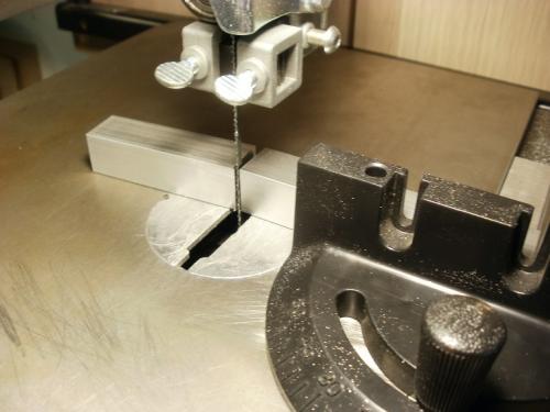
A length of tubing was cut a bit longer than the space for the chassis.

One end was sanded square to measure and mark all the holes from that end when the part was flipped 90 degrees.

The wheelbase had to be figured out first. Tires were glued onto the aluminum wheels and trued on a tire-truing machine to fit the car. That's another thread in itself.
The wheels were laid down on a bench or table. The body was slid into the wheels until they centered themselves in the wheel arches. Then the distance between the center of the axles was measured. It doesn't work this easily for every car. But it will usually be close. Measure three times if needed. It's worth triple checking.


The guide and body posts need to be figured out by checking how much room you have inside the body. Don't forget to allow extra distance for the guide to turn.
I made a drawing for each car before drilling anything.

Several different cars may show up for this tutorial. It's not about any one car. This method can be adapted to many different bodies.
Now that we have measurements and metal. The measurements need to be scribed onto the aluminum.
A permanent marker was used to mark the general area where the lines would go. This helps to see the scribed lines clearly. The metal was measured with a digital calliper. The calliper was set to half the distance. Then another larger piece of metal was used to set the callipers against while the callipers were slid down the tubing to scribe a line. Then the 3/4" tubing was flipped 180 degrees and scribed again. The small distance between the two lines is the closest thing to center I can get without more complicated measuring equipment.

The tubing was turned 90 dregrees, and the guide/body post distances were marked.

Here is the aluminum tubing measured and ready for drilling.

The next section will show what tools are required, and how to go about the process of machining.
Brass, wire, and solder were strange to me. I was more comfortable with a drill press, disk sander, and bandsaw.
We have a store in Canada called Home Depot.
I have searched their metal rack many times before for other reasons. Might it be possible to find something that would work for a slot car?
Make sure it's 3/4" inch square aluminum by 1/16" wall thickness. I have recently found out that there are a lot of thin imposters out there.
A length of tubing was cut a bit longer than the space for the chassis.
One end was sanded square to measure and mark all the holes from that end when the part was flipped 90 degrees.
The wheelbase had to be figured out first. Tires were glued onto the aluminum wheels and trued on a tire-truing machine to fit the car. That's another thread in itself.
The wheels were laid down on a bench or table. The body was slid into the wheels until they centered themselves in the wheel arches. Then the distance between the center of the axles was measured. It doesn't work this easily for every car. But it will usually be close. Measure three times if needed. It's worth triple checking.
The guide and body posts need to be figured out by checking how much room you have inside the body. Don't forget to allow extra distance for the guide to turn.
I made a drawing for each car before drilling anything.
Several different cars may show up for this tutorial. It's not about any one car. This method can be adapted to many different bodies.
Now that we have measurements and metal. The measurements need to be scribed onto the aluminum.
A permanent marker was used to mark the general area where the lines would go. This helps to see the scribed lines clearly. The metal was measured with a digital calliper. The calliper was set to half the distance. Then another larger piece of metal was used to set the callipers against while the callipers were slid down the tubing to scribe a line. Then the 3/4" tubing was flipped 180 degrees and scribed again. The small distance between the two lines is the closest thing to center I can get without more complicated measuring equipment.
The tubing was turned 90 dregrees, and the guide/body post distances were marked.
Here is the aluminum tubing measured and ready for drilling.
The next section will show what tools are required, and how to go about the process of machining.

![[+]](https://slotracer.online/community/images/bootbb/collapse_collapsed.png)