

30th-Aug-25, 07:48 PM
HARDWARE FINAL RE-ASSEMBLY
Step 12: Next, it’s time to replace the 16 way ribbon connection we removed earlier. This involves attaching a 16 way header to the main board. It’s standard 0.1 inch pitch (i.e. 2.54mm pitch).
I use small PCBs with FFC 8-way connectors and 8-way FFC cables to make the 16 connections to the LEDs and top panel buttons.
The FFC assembly is shown in the next photo.
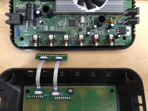
Next, the FFC assembly is shown plugged into the 16 way header. This is now unplug-able and replug-able for future maintenance.

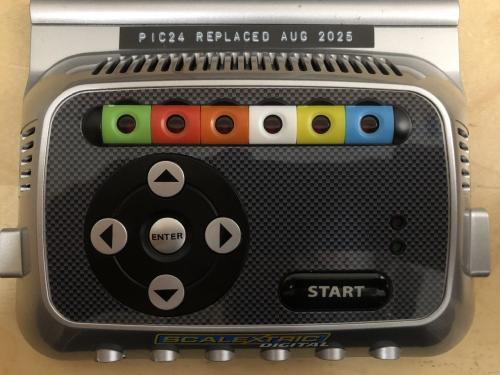
Step 13: The hardware is now re-assembled and ready for installation of firmware v1.009 and system testing.
c
Step 12: Next, it’s time to replace the 16 way ribbon connection we removed earlier. This involves attaching a 16 way header to the main board. It’s standard 0.1 inch pitch (i.e. 2.54mm pitch).
I use small PCBs with FFC 8-way connectors and 8-way FFC cables to make the 16 connections to the LEDs and top panel buttons.
The FFC assembly is shown in the next photo.
Next, the FFC assembly is shown plugged into the 16 way header. This is now unplug-able and replug-able for future maintenance.
Step 13: The hardware is now re-assembled and ready for installation of firmware v1.009 and system testing.
c
![[+]](https://slotracer.online/community/images/bootbb/collapse_collapsed.png)