Posts: 315
Threads: 23
Likes Received: 553 in 239 posts
Likes Given: 124
Joined: Oct 2023
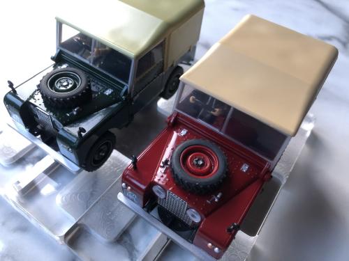
Now that Scalextric has released a second Land Rover (the poppy red version) there is an exciting opportunity to create a digital racing pair. One green and one red :)

The digitisation looks straight forward except for one detail - the high chassis clearance and hence the requirement for careful positioning of the Infra-Red LED.
I have no doubt there are many possible solutions - I plan to share mine over the next few posts.
The motivation here is to see two of these Land Rovers racing on a digital track, changing lanes, pitting etc etc and all with the ultimate objective… to be first to cross the finish line.
C
(This post was last modified: 10th-Jun-24, 11:05 PM by
Dr_C.)
Posts: 1,917
Threads: 116
Likes Received: 3,135 in 1,289 posts
Likes Given: 2,707
Joined: Sep 2020
Location A small igloo in Canada
My money is on the Land Rover to take the checkered flag!

Did I win anything?
Posts: 315
Threads: 23
Likes Received: 553 in 239 posts
Likes Given: 124
Joined: Oct 2023
ha ha, yes, but which one? green or red?
c
Posts: 1,917
Threads: 116
Likes Received: 3,135 in 1,289 posts
Likes Given: 2,707
Joined: Sep 2020
Location A small igloo in Canada
Red and green are the colours that colour-blind people often have trouble with.
They would likely say the "red/green" one would win.

Posts: 315
Threads: 23
Likes Received: 553 in 239 posts
Likes Given: 124
Joined: Oct 2023
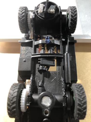
First, I drilled two 1mm holes in the lowest point of the chassis as shown. This is to be followed by some hot glue to hold the 3mm LED in place and then some 14 AWG silicone wire attached from the interior side. I chose silicone wire to protect the insulation from heat from the motor which is very close.


(This post was last modified: 11th-Jun-24, 01:55 PM by
Dr_C.)
Posts: 315
Threads: 23
Likes Received: 553 in 239 posts
Likes Given: 124
Joined: Oct 2023
Both Land Rovers are now fully prep’d ready for fitment of the digital decoders.
1/ dual 1mm holes drilled in both chassis.
2/ IR LEDs fitted and secured with black hot glue.
3/ LED wiring fitted under the motor, emerging on the port side.
4/ yellow/green silicone wiring fitted at pick-up.
5/ red/black silicone wiring fitted to motor while retaining the 100nF noise suppression capacitor.
Next step will be to install a digital decoder into each car. This could be a new style C8516 with black casing and four pin socket removed. In my case I will use my slightly smaller decoders which also include lighting circuits for brake lights.
I’m looking forward to some digital racing with this unlikely pair whose classic design goes back to the late 1940’s.
c
(This post was last modified: 11th-Jun-24, 06:35 PM by
Dr_C.)
![[+]](https://slotracer.online/community/images/bootbb/collapse_collapsed.png) •
•


![[+]](https://slotracer.online/community/images/bootbb/collapse_collapsed.png)

