8th-Apr-21, 04:52 PM
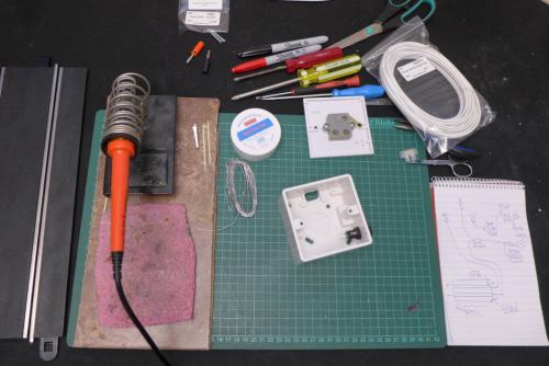
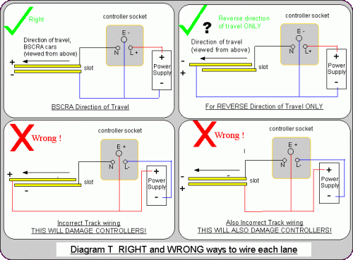
When I do any wiring or soldering, I like to draw my own wiring picture with pen and paper. It’s not anything technical – it’s something that has to make sense to me. I might just be copying a diagram I’ve found online (like the BSCRA diagrams), but the process of drawing helps me decide whether I understand what I’m trying to do. If I don't, it's probably not safe to continue. I can also refer to it on my bench as I work, rather than have to look at a screen. Diagram done, I assemble all my tools and components…

Most of the connections in the box are screw terminals and the only soldering is in and out of the fuse holder, two wires to the track and a wire to each of the banana plugs. However, I am going to tin (cover with a layer of solder) the ends of the wires going into the screw terminals – not entirely necessary, but it will make the wires more robust. That means measuring up and cutting the lengths of wire that I’ll need – as per the wiring diagram. Within the box, I will use longer wires than I need from the fuse holder to the L terminal and from the E terminal to the terminal block. I’ll do this so not to pull on the connections – and there is a lot of room in the 47mm deep box.
There are plenty of online guides to soldering – most of them really good. My dad taught me when I was a teenager (soldering was part of his job), but I’ve since picked up plenty of useful tips from various online tutorials. I clean surfaces (and soldering iron tip), use flux paste, tin each surface before I join and don’t skimp on the solder. I also work on one component at a time and keep things simple. I’d normally use colour-coded wire, but the wiring box is something I’m familiar with and I’ll use the same twin wires – one has a black line on it – which will be the positive (usually red) power wire.

The positive wire from the red banana plug at the power supply, runs through the fuse and to the L terminal and then to the positive rail on the track via the N terminal – the power has gone through the controller from L to N. Do check for the N and L on the terminals. The BSCRA diagram shows the three-pin plate from the top down – we wire it from the bottom.
The other – negative – wire goes from the black banana plug to the loose terminal connector in the box… Here it meets a wire from the E terminal (the brake wire of the controller) and continues to the negative rail on the track.
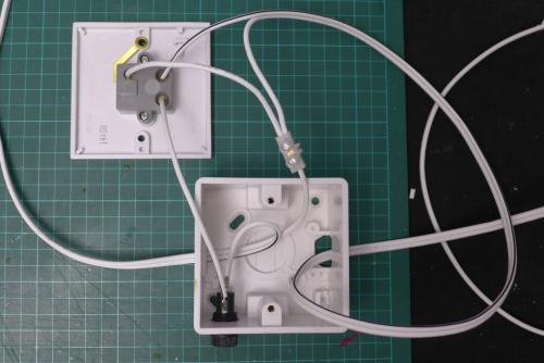
Here is the box wired up, with the only soldered joins on the fuse holder...

Can you see how the actual wiring matches the diagrams?
Here's the same picture annotated...

The next step is to solder the banana plugs to the end of the long 'power-in' cable - and then solder the ends of the shorter 'power-out' cable to the underside of the track.
Most of the connections in the box are screw terminals and the only soldering is in and out of the fuse holder, two wires to the track and a wire to each of the banana plugs. However, I am going to tin (cover with a layer of solder) the ends of the wires going into the screw terminals – not entirely necessary, but it will make the wires more robust. That means measuring up and cutting the lengths of wire that I’ll need – as per the wiring diagram. Within the box, I will use longer wires than I need from the fuse holder to the L terminal and from the E terminal to the terminal block. I’ll do this so not to pull on the connections – and there is a lot of room in the 47mm deep box.
There are plenty of online guides to soldering – most of them really good. My dad taught me when I was a teenager (soldering was part of his job), but I’ve since picked up plenty of useful tips from various online tutorials. I clean surfaces (and soldering iron tip), use flux paste, tin each surface before I join and don’t skimp on the solder. I also work on one component at a time and keep things simple. I’d normally use colour-coded wire, but the wiring box is something I’m familiar with and I’ll use the same twin wires – one has a black line on it – which will be the positive (usually red) power wire.
The positive wire from the red banana plug at the power supply, runs through the fuse and to the L terminal and then to the positive rail on the track via the N terminal – the power has gone through the controller from L to N. Do check for the N and L on the terminals. The BSCRA diagram shows the three-pin plate from the top down – we wire it from the bottom.
The other – negative – wire goes from the black banana plug to the loose terminal connector in the box… Here it meets a wire from the E terminal (the brake wire of the controller) and continues to the negative rail on the track.
Here is the box wired up, with the only soldered joins on the fuse holder...
Can you see how the actual wiring matches the diagrams?
Here's the same picture annotated...
The next step is to solder the banana plugs to the end of the long 'power-in' cable - and then solder the ends of the shorter 'power-out' cable to the underside of the track.

![[+]](https://slotracer.online/community/images/bootbb/collapse_collapsed.png)