
Thread Rating:
  • 0 Vote(s) - 0 Average
  • 1
  • 2
  • 3
  • 4
  • 5

Experimenting with Sensored Brushless Motors
#71

The first batch of SENSORED brushless driver PCBs as shown earlier are intended as miniaturised evaluation/development boards - and importantly they can fit inside a digital slot-car. As development boards that’s why they include a couple of diagnistics 8 way FFC sockets too.

But meanwhile I designed a variant which is smaller and is closer to the final design. And guess what? they have arrived from the manufacturer super fast.

These new boards similarly attach directly to the motor; piggy-back style.

The photo below shows an NSR angle winder mount, a 3500Kv sensored brushless motor and two of the latest brushless motor driver circuit boards. They will all fit together in due course.

The SENSORED brushless motor has a diameter of 15mm, a length of 25mm and a 2mm shaft diameter. The fixing points match those of standard slot car motors which avoids any requirement for mounting adapters.

The new circuit boards as shown measure 15mm x 20mm.
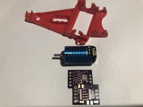
   

Note: on the underside of the circuit board there is a 6x3 matrix of small square pads - these are for the ‘configuration’ jumpers for the Hall sensor ICs. Small but not too small ;)

Thanks for your interest in this thread and the work reported here.

c
[+] 1 member Likes Dr_C2's post
Quote
#72

This project, hopefully, will bring a completely ‘new’ motor and power train to the digital slot car hobby. 

Will it be a game changer?

It’s too early to tell… but interesting to explore anyway :)

c
[+] 2 members Like Dr_C2's post
Quote
#73


Four assembled driver modules for SENSORED brushless motors. To complete they each need a 5 pin 1.25mm pitch micro JST socket to be added for interfacing with the motors’ internal Hall sensor ICs. Soon they will be complete.

Once the sockets arrive, motors will be powered up.

No complications detected so far … all is looking good ;)

c
[+] 2 members Like Dr_C2's post
Quote
#74

Interesting learning… the Texas Instruments evaluation board runs the motors perfectly.

So, this evening I started testing my small custom designed evaluation/ development boards. First I wanted to see that the internally generated 5V is driving the Hall sensor ICs correctly… but… the voltage rail measured zero V not 5V. A problem! … or so I thought. A couple of hours this evening spent trouble-shooting.

At last the answer. 

When there is no throttle signal and if the motor is not turning, guess what? 

The IC goes into sleep mode and adjusts to minimise current draw including switching off the 5V internal regulator. Too clever. So there was no problem after all :)

Testing continues.

c
[+] 2 members Like Dr_C2's post
Quote
#75

Is the throttle signal for the motor driver chip PWM or something else eg SBus, custom etc?
Quote
#76

(4th-Aug-25, 10:06 PM)Drifter2 Wrote:  Is the throttle signal for the motor driver chip PWM or something else eg SBus, custom etc?

Hi Drifter2, the IC itself requires a PWM signal with repetition frequency in the range 15-100kHz. This requirement is too high to be directly driven by most decoder PWM motor drive signals except of course D132. Most are in the range 170-1000Hz.

My decoders based on the ATtiny3224/6 should be fine using their timers with embedded PWM function. Alternatively I’ve added a separate ATtiny3226 (as an option) onto the brushless driver boards which in due course should provide four additional motor drive methods:

1/ upshift the PWM frequency
2/ motor/brake commands over SPI.
3/ motor/brake commands over I2C.
4/ r/c pulse train conversion.

Many thanks for the question :)

c
[+] 1 member Likes Dr_C2's post
Quote
#77

The custom designed evaluation/development boards appear to be functioning!

So far the boards have been tested for correct function of the motor drive circuit. This testing has been carried out at bench level using a small signal generator to provide the 15kHz PWM motor drive waveform. They spool up to full rpm and are smoothly controllable across the rpm range. A very good result.


Next I will test correct function of the brakes - here the objective is to test for fully adjustable braking strength - again using PWM signals.

The most important aspect of the evaluation/development boards is that they are small enough to fit inside 1/32 scale digital slot-cars.

After brake testing they will be fitted into digital slot-cars for track level trials.

Exciting…

c
[+] 1 member Likes Dr_C2's post
Quote
#78


Here is the 15mm x 20mm SENSORED BL motor driver module. The photo was taken after the module had been put under test with a BL motor and spooled up to max rpm.

At the moment the driver module connects to the motor windings with a 3 pin header socket. It connects to the Hall sensor ICs via the micro-JST 1.25mm pitch 5 way socket.

We are fast approaching final design. So far there have been a few learning points:

1/ Changing motor direction is not as simple as brushed motors where reversing two wires is all that is required.

2/ The tiny jumper adjustments using 0402 0 Ohm parts does work successfully but it is tediously time consuming to implement by hand. And, since only two distinct configuration patterns are needed, the simple answer is two pcbs pre-configured with each of the patterns.

3/ Learning that the internally generated 5V is auto switched off whenever the motor stops has been important and cautions against its use beyond powering the Hall sensor ICs.

All good learning and the fact these small boards successfully spool-up my SENSORED BL motors, and with fine control, represents significant progress.

c
Quote
#79

Hmm, RC brushless motors normally only need two of the three wires between the motor and ESC swapping to reverse.

Life is like a box of Slot cars... Cool Drinkingcheers
Quote
#80

(10th-Aug-25, 11:29 AM)Kevan Wrote:  Hmm, RC brushless motors normally only need two of the three wires between the motor and ESC swapping to reverse.
Yes - that’s certainly true for UNSENSORED brushless motors of which I have many, and a fair bit of experience using them in the world of aero-modelling.

But here we are talking SENSORED brushless motors which at the very least would require the Hall sensor signals to be re-ordered to match. But for what is known as trapeizoidal waveform drive it appears even more complicated as the sensor positions need to account for a 45 degree offset which is different for each direction of rotation.

Maybe all of this is handled in the ESC in R/C cars as per your experience Kevan?

c
Quote


Possibly Related Threads...
Thread / Author Replies Views Last Post
Last Post by Dr_C2
30th-Sep-25, 08:42 AM
Last Post by Dr_C2
11th-Dec-24, 10:20 AM
Last Post by Dr_C2
27th-Oct-23, 12:37 AM

Forum Jump:


Users browsing this thread: 1 Guest(s)