Serial Interface Wiring
KSerial Interface Wiring
The RS-232 Serial interface port can be used to time and count laps with a minimum of external electronic circuitry. The wiring diagrams below illustrate the basic schematic required.
KDB-25 Connector
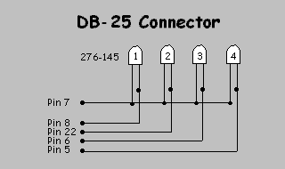
The first wiring diagram illustrates the interface cable required to build an interface that will work with the larger DB-25 connector found on many personal computers
KDB-9 Connector
The second wiring diagram illustrates the cable required to build an interface that will work with the smaller DB-9 connector found on many lap top computers.
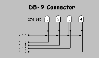
KThe photo-cells in the wiring diagrams above are available at any Radio Shack retail outlet for less than $2.00 each. Ask the clerk for RS Part No. 276-145. Purchase one photo-cell for each lane on your raceway. The longer lead (Emitter) is connected to the common signal ground (Pin 5 or 7).
KLane Assignments
The table below lists the lane number/pin assignments for the Serial Port connectors
Track DB-25 DB-9
Lane 1 Pin 8 Pin 1
Lane 2 Pin 22 Pin 9
Lane 3 Pin 6 Pin 6
Lane 4 Pin 5 Pin 8
Created with the Personal Edition of HelpNDoc: Easily create Web Help sites