Printer Interface Wiring
KPrinter Interface Wiring
The Parallel Printer interface port can be used to time and count laps with a minimum of external electronic circuitry. The wiring diagrams below illustrate the basic schematic required.
KTrakMate Compatibility
The first wiring diagram illustrates the interface cable required to build an interface that will work with either Lap Timer 2000 or TrakMate software.
This is the recommended printer interface. If you build this version of the printer interface make sure the TrakMate Compatibility settingLap Timer Ports is enabled.

KVRS Compatibility
The second wiring diagram illustrates the cable required to build an interface that will work with either Lap Timer 2000 or VRS software. This wiring diagram is included to maintain compatibility with earlier releases of Lap Timer 2000.
If you have not built or purchased a cable yet it is recommended that you build the TrakMate compatible cable illustrated above instead of the VRS version. If you elect to build the VRS version of the printer interface make sure the TrakMate Compatibility settingLap Timer Ports is disabled.
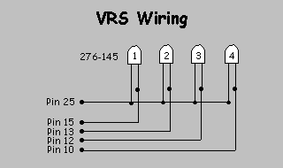
KThe photo-cells in the wiring diagrams above are available at any Radio Shack retail outlet for less than $2.00 each. Ask the clerk for RS Part No. 276-145. Purchase one photo-cell for each lane on your raceway. The longer lead (Emitter) is connected to the common signal ground (Pin 25).
KYou may also purchaseCable Order Form a pre-made Printer Interface Cable if you would prefer not building your own interface electronics. Secure on-line credit card purchases can be made by using the Help | Purchase Interface Cables menuHelp Menu command.
Pre-made and tested Printer interface cables that you purchase will conform to the TrakMate Compatibility standards.
KLane Assignments
The table below lists the lane number/pin assignments for the Printer Port connector
Track TrakMate VRS
Lane 1 Pin 10 Pin 15 (Red)
Lane 2 Pin 11 Pin 13 (White)
Lane 3 Pin 12 Pin 12 (Blue)
Lane 4 Pin 13 Pin 10 (Yellow)
Relay Pin 2 Pin 2 (Optional)
Track Call Pin 15 N/A (Optional)
Ground Pin 25 Pin 25 (All Lines)
KTrack Power Relay
Pins 2 and 25 can be used to trigger a small DC track power relayTrack Relay Wiring. Make sure the Track Power Relay Installed settingLap Timer Ports is enabled if you connect a relay to Lap Timer 2000.
KTrack Call Switch
Pins 15 and 25 can be used to sense a track call switch. Make sure the Track Call Switch Installed settingLap Timer Ports is enabled if you use a track call switch with Lap Timer 2000.
Signal Ground Lines
Most printer interface ports uses lines 18 through 25 for signal grounds. You can use a separate line for each sensor if you would prefer to not solder four ground lines to the single pin 25.
Created with the Personal Edition of HelpNDoc: Easily create EPub books