Thread Rating:
  • 0 Vote(s) - 0 Average
  • 1
  • 2
  • 3
  • 4
  • 5

Scalextric Pro - wooden track build
#1

Hello,

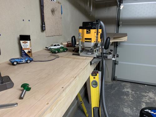
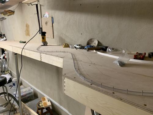
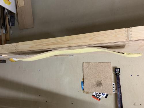
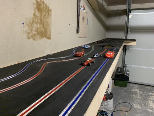
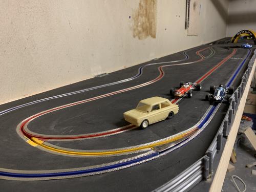
This is my first post here, I've been building a wooden slot track for quite a while as per these photos. It took about a month to build over a few evenings and weekends in Jan 2019. The basic plan is two lane routed track that uses Scalextric digital technology to drive lane flippers and run races via the iPad app.

The track curves were designed with the existing Scalextric flippers in mind so there are two overtaking spots and one pit lane.

Flippers work well and the digital or analogue also runs cars around quite happily.

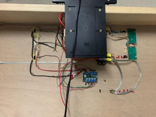
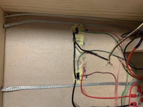
The lap detection however are still a work in progress, the lanes are further apart than Scalextric planned which meant I had to cut the PCBs and re-solder them together. More on that later...


Dave
[+] 5 members Like edged's post
Quote
#2

And so onto the problem, no idea if anyone here can help. I'm trying to replace the opto couplers with these:

https://www.truspeed.co.uk/products/8mm-...ack-sensor
https://www.truspeed.co.uk/collections/s...nterface-1

But I've tried a few things to get it plumbed into the Scalextric head unit for the Pro but it's doesn't count laps. The out of the box Scalextric sensors do not like being de-soldered from the board and they fail. 

Does anyone know what the pinouts are needed to get this little box of tricks communicating with the Scalextric system? there are four wires for each sensor module in the Scalextric system and I think they are as follows, but clearly not as they don't work!

yellow = gnd
black = +3v
red = lane 1
gray = lane 2

Any info anyone might have would be a massive help!
[+] 1 member Likes edged's post
Quote
#3

Hello Edged and welcome to SlotRacer.  Wavegreen

That's a very cool track. I apologize that I cannot answer your question as I am old school analog.

But I look forward to seeing the end result. Routed digital sounds very interesting.  Thumbup

I'm certain someone will rise to the cause and answer your question.
[+] 1 member Likes KensRedZed's post
Quote
#4

Hi Dave - the track looks great!

I have never taken an ARC Pro base apart and tinkered with it - I’m only familiar with the functionality of the system out of the box. Starting from basics - which you may already have done - check the following...

For lap counting in digital mode, the powerbase reads a black guide going through an optosensor and then searches for the car’s LED with a second upward-facing sensor. If either of these fails, no laps are counted. If you only have the guide sensor, laps cannot be counted in digital mode (although they will be in analogue mode). And then there are the software issues of lap counting: https://slotracer.online/arc-pro-guide/preparation.html

If that all seems in order, I wonder if the Truspeed hardware is compatible? In other words, whether the output of the Truspeed interface can be read by ARC Pro at the point you are inputting that signal to ARC Pro circuitry. Is it actually doing the same job as similar components on the ARC Pro board?
[+] 1 member Likes woodcote's post
Quote
#5

Thanks for the welcome both! 

I've just been doing some bench testing with an old Arc Air powerbase and a multi-meter. I think my assumption that a +5v pulse to a certain pin on the sensor connector is the problem, it's not how the Scalextric system detects the guide blade; instead what seems to be the case is the following:

red = gnd
white = +2v with no car on lane 1
white = 0v with a car's guide blade blocking the IR sensor on lane 1

Back to the instructions for the track interface for 'negative going' - I think this is more likely the right setting to fool the Scalextric unit...
[+] 3 members Like edged's post
Quote
#6

Hi edged,

Welcome here and thank you for sharing the photos of your track build process.

rallyhub Thumbup
Quote
#7

Hi edged, a really beautifully crafted track so hope you get the sensor wiring sorted very soon.

I am wondering whether you plan to use digital only or whether you wish to keep analog functions too?

If digital only I can share ideas to help you sort the wiring. If you want both digital and analog there are some extra challenges.

For digital only you only require the upward facing ID sensing phototransistors at the lap counting end and the blade detectors at the other end. The upward facing ones are the ones you will be having difficulty removing... for these I can suggest alteratives. For the blade sensor at the other end... probably cutting the pcb in half and wiring between the two is probably easiest.

Hope this helps...

c
[+] 2 members Like Dr_C's post
Quote
#8

Thanks Dr_C, I've managed to get it working now. The key was configuring the opto sensor interface for 'Negative Going', this essentially provides +5v to each of the four scalextric lane detection wires and when the guide breaks the beam the +5v drops to 0v and the system is triggered correctly.

For anyone interested and for future reference the wiring required was:

wire the opto sensor interface for Negative Going
flip the switch on the interface to Negative Going

scalextric ribbon yellow - common ground for the opto sensor interface
scalextric ribbon red (lane 1) - lane 1 on the opto sensor interface
scalextric ribbon black (lane 2) - lane 2 on the opto sensor interface

repeat for the other two sensors.


The track works timing and counting laps for races in both analog and digital modes. One oddity of the digital mode is that neither car can get a whole lap ahead it seems. The other car has to come around and count a lap before the other can do so. I don't remember that being a feature of the Arc Pro system but maybe it is?
Quote


Possibly Related Threads...
Thread / Author Replies Views Last Post
Last Post by woodcote
23rd-Apr-25, 08:03 AM

Forum Jump:


Users browsing this thread: 1 Guest(s)