

9th-Nov-24, 03:00 PM
As mentioned, I hope this will be a simple project to complete.
The approach is as follows:
1/ Two ID sensors will be positioned on each of two lanes with a known separation.
2/ A sensor hub using firmware which has already been developed will read the arrival time at each sensor, plus the car’s ID. IDs are in the range 1-36.
3/ From this information, the transit speed and ID can then be displayed as cars traverse the dual sensor zone.
4/ As mentioned the plan here is to use 100mm tall (4 inch) 7 segment displays. Two digits for ID and then four digits for speed in m/s in the format ‘ZZ.ZZ’.
So all that is left to complete this project is the design and construction of the display modules.
I will be using a simple ‘clocked serial data’ approach which is fairly standard. This approach typically uses a 74HC596 or if higher current drive is required then a TPIC5D596. I will be using the latter.
This has become a nice little high school grade project :)
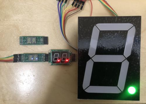
A simple test set-up is shown below. The red dual display is a low cost commercial product. The small white display uses one of my PCB designs, and the large green display is using stand-alone TPIC5D596 driver board. I will design a simple back-plane PCB for these large displays to keep wiring looms to a minimum.
c
The approach is as follows:
1/ Two ID sensors will be positioned on each of two lanes with a known separation.
2/ A sensor hub using firmware which has already been developed will read the arrival time at each sensor, plus the car’s ID. IDs are in the range 1-36.
3/ From this information, the transit speed and ID can then be displayed as cars traverse the dual sensor zone.
4/ As mentioned the plan here is to use 100mm tall (4 inch) 7 segment displays. Two digits for ID and then four digits for speed in m/s in the format ‘ZZ.ZZ’.
So all that is left to complete this project is the design and construction of the display modules.
I will be using a simple ‘clocked serial data’ approach which is fairly standard. This approach typically uses a 74HC596 or if higher current drive is required then a TPIC5D596. I will be using the latter.
This has become a nice little high school grade project :)
A simple test set-up is shown below. The red dual display is a low cost commercial product. The small white display uses one of my PCB designs, and the large green display is using stand-alone TPIC5D596 driver board. I will design a simple back-plane PCB for these large displays to keep wiring looms to a minimum.
c
