

11th-Mar-24, 06:27 PM
Installation of the DSD TECH SH-U11F
1/ Remove the four screws on the back of the DSD TECH opto-isolator, remove the cover, and then fit one of the included jumpers as shown in the photo below. Then re-assemble.

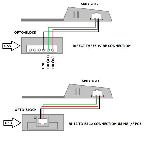
2/ Next, connect three short wires between the DSD TECH opto-isolator and the RJ12 socket on the APB C7042. Take care to wire correctly as one of the pins carries +12V so should NOT be connected by error.
I can provide a simple connector board which eliminates any need for attention to wiring details and the use of an RJ12 crimping tool. This is shown on the right hand side in the above photograph.
The wiring diagram for direct wiring or using the connector board is shown next.
3/ Power-up and the job is done.!
1/ Remove the four screws on the back of the DSD TECH opto-isolator, remove the cover, and then fit one of the included jumpers as shown in the photo below. Then re-assemble.
2/ Next, connect three short wires between the DSD TECH opto-isolator and the RJ12 socket on the APB C7042. Take care to wire correctly as one of the pins carries +12V so should NOT be connected by error.
I can provide a simple connector board which eliminates any need for attention to wiring details and the use of an RJ12 crimping tool. This is shown on the right hand side in the above photograph.
The wiring diagram for direct wiring or using the connector board is shown next.
3/ Power-up and the job is done.!
![[+]](https://slotracer.online/community/images/bootbb/collapse_collapsed.png)