26th-Feb-21, 07:34 AM
Dragstrip shutdown area: Here's one I did earlier.
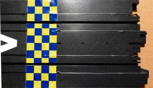
From the top, on the left the rail is ripped from a straight to create a dead electrical section in the direction of travel, here to the right, where I've attached a shorted out 3" straight that can be seen in the right hand photo. You can just make out the tops of the 'staples' I inserted across the rails to create the short.


From the underside, the left shows the complete 'shutdown' strip. The 'staples' were bent up from bits of the rail ripped from the dead section. On the right the dead section and shorted out piece were glued together. The 'U' shaped staples were inserted alongside the rails after first pushing a knifeblade (preferred) or jewellers screwdriver through just enough to allow 'wiggle-room' so the staples fit tightly against the rails.
No soldering was required.
A dab of superglue at the centre spot of each is just for peace of mind. They are such a tight fit they shouldn't come out though.


The markings on the track surface are partly to help identify the shutdown strip in a boxful of regular track, to show the direction of travel and mark the start of the braking zone. It was extremely effective in reducing the shutdown area and bringing cars safely to a halt on our 1/64th scale Quarter Mile (20.625'.)
From the top, on the left the rail is ripped from a straight to create a dead electrical section in the direction of travel, here to the right, where I've attached a shorted out 3" straight that can be seen in the right hand photo. You can just make out the tops of the 'staples' I inserted across the rails to create the short.
From the underside, the left shows the complete 'shutdown' strip. The 'staples' were bent up from bits of the rail ripped from the dead section. On the right the dead section and shorted out piece were glued together. The 'U' shaped staples were inserted alongside the rails after first pushing a knifeblade (preferred) or jewellers screwdriver through just enough to allow 'wiggle-room' so the staples fit tightly against the rails.
No soldering was required.
A dab of superglue at the centre spot of each is just for peace of mind. They are such a tight fit they shouldn't come out though.
The markings on the track surface are partly to help identify the shutdown strip in a boxful of regular track, to show the direction of travel and mark the start of the braking zone. It was extremely effective in reducing the shutdown area and bringing cars safely to a halt on our 1/64th scale Quarter Mile (20.625'.)

![[+]](https://slotracer.online/community/images/bootbb/collapse_collapsed.png)