

13th-Jul-24, 12:27 PM
Dyno 2.0
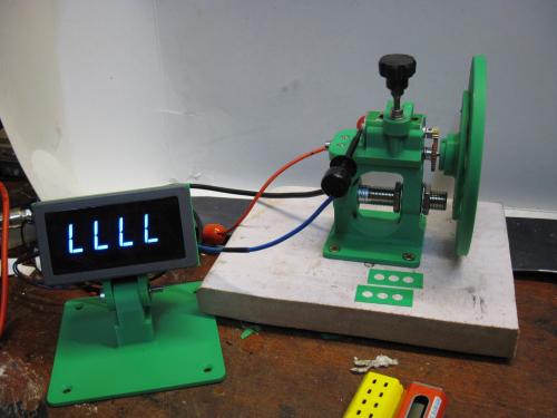
Designed the above Dyno a while ago, using a propriety hall effect sensor and digital counter for testing motors for club racing. From this testing, it was found that the motor rpm is effectively unloaded as the motor will spool the flywheel to near maximum unloaded rpm of the motor. Changing the flywheels for heavier ones only gives a perception of the motors ability to operate under load as the spool time is not measurable without going into data logging. The missing element is some form of load that is not overcome by inertia, and the simplest form is using a mechanical brake block or a fan pushing air.
The solution I went with is to couple a parasitic motor geared to the other end of flywheel shaft, the connections of which are then connected to a switched brake pot. The pot selects either open connection (No load), or steps through a braking effect via diodes or resistors and hence will load the test motor. This has the advantage over the mechanical forms as it is adjustable on the fly to suit different motors with preset steps.
The initial brake circuit used a diode chain but after I burnt out a set of diodes went over to some spare 6 ohm metal case high wattage resistors wired for 6, 9, 12 & 15 ohms on a rotary pot. These need to be 10W+ rated as the load is applied for a greater duration than conventional brake pots would see in a controller.
Parasitic motor used is a ball raced Scaleauto blue 18K rpm with low ratio gearing, chosen for low torque and the ball raced armature so that the ‘zero’ load is as low as possible. The cradle will take any boxer long or short can or an S can/FC130 can drive (with screw mounting holes).
The tower and motor cradle from the original design has been modified to take the parasitic motor mounted under the motor cradle, plus the test motor clamp screw hole has been changed to take a brass insert instead of relying on the plastic thread which fails with repeated use. The brass inserts are available from Ebay and can be fitted using a soldering iron, by locating the iron tip in the insert and pushing down in to the cradle hole. The test cradle will take Boxers, Flat 6's and S cans using the packing pieces shown.
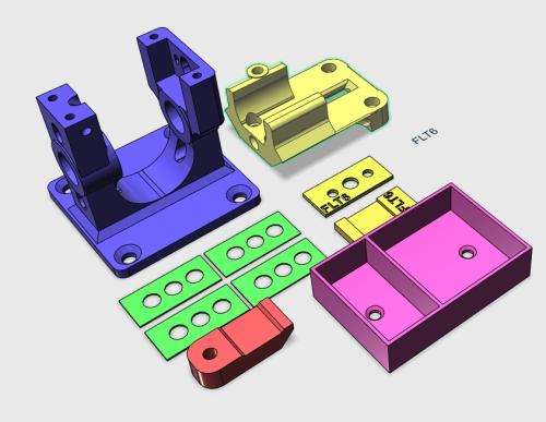
The sensor wheel has been modified to take a Fly/PSR/NSR 8mm x 5mm round magnet in a profiled pocket as these work just as well as the supplied magnet and most of us have stock stuck to the nearest metal surface.
Final set of parts is a DVM tower which takes a propriety DVM module to monitor voltage/current, the brake pot tower with banana plug sockets for monitoring voltage and current and a tray to put the motor packing spacers in.
Dyno V2.0
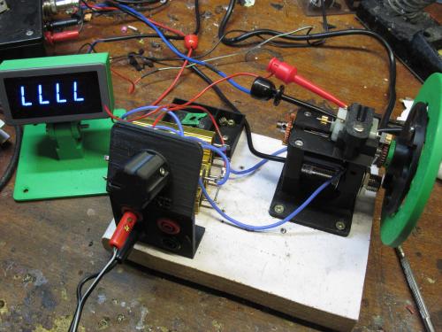
In use motors, are spooled up unloaded to reach a steady rpm, then the brake pot is switched in to ramp up the load to a setting appropriate for that type of motor. The test motor rpm will then fall to a ‘loaded’ value which can be compared across the range of motors to be tested.
Below is the V2.0 STLfiles.
Parts list is on the original post here
https://slotracer.online/community/showt...p?tid=3871
DVM panel meters
https://www.ebay.co.uk/sch/i.html?_from=...&_osacat=0
Cheers
John
Designed the above Dyno a while ago, using a propriety hall effect sensor and digital counter for testing motors for club racing. From this testing, it was found that the motor rpm is effectively unloaded as the motor will spool the flywheel to near maximum unloaded rpm of the motor. Changing the flywheels for heavier ones only gives a perception of the motors ability to operate under load as the spool time is not measurable without going into data logging. The missing element is some form of load that is not overcome by inertia, and the simplest form is using a mechanical brake block or a fan pushing air.
The solution I went with is to couple a parasitic motor geared to the other end of flywheel shaft, the connections of which are then connected to a switched brake pot. The pot selects either open connection (No load), or steps through a braking effect via diodes or resistors and hence will load the test motor. This has the advantage over the mechanical forms as it is adjustable on the fly to suit different motors with preset steps.
The initial brake circuit used a diode chain but after I burnt out a set of diodes went over to some spare 6 ohm metal case high wattage resistors wired for 6, 9, 12 & 15 ohms on a rotary pot. These need to be 10W+ rated as the load is applied for a greater duration than conventional brake pots would see in a controller.
Parasitic motor used is a ball raced Scaleauto blue 18K rpm with low ratio gearing, chosen for low torque and the ball raced armature so that the ‘zero’ load is as low as possible. The cradle will take any boxer long or short can or an S can/FC130 can drive (with screw mounting holes).
The tower and motor cradle from the original design has been modified to take the parasitic motor mounted under the motor cradle, plus the test motor clamp screw hole has been changed to take a brass insert instead of relying on the plastic thread which fails with repeated use. The brass inserts are available from Ebay and can be fitted using a soldering iron, by locating the iron tip in the insert and pushing down in to the cradle hole. The test cradle will take Boxers, Flat 6's and S cans using the packing pieces shown.
The sensor wheel has been modified to take a Fly/PSR/NSR 8mm x 5mm round magnet in a profiled pocket as these work just as well as the supplied magnet and most of us have stock stuck to the nearest metal surface.
Final set of parts is a DVM tower which takes a propriety DVM module to monitor voltage/current, the brake pot tower with banana plug sockets for monitoring voltage and current and a tray to put the motor packing spacers in.
Dyno V2.0
In use motors, are spooled up unloaded to reach a steady rpm, then the brake pot is switched in to ramp up the load to a setting appropriate for that type of motor. The test motor rpm will then fall to a ‘loaded’ value which can be compared across the range of motors to be tested.
Below is the V2.0 STLfiles.

Parts list is on the original post here
https://slotracer.online/community/showt...p?tid=3871
DVM panel meters
https://www.ebay.co.uk/sch/i.html?_from=...&_osacat=0
Cheers
John
Mr Fit for Function.
![[+]](https://slotracer.online/community/images/bootbb/collapse_collapsed.png)
