That's a long time since April! Not a huge amount has happened apart from a lot of running and some subsequent tweaking.
A big test was the TR7 proxy, where the hill got some sheets thrown at it for decoration and some quick cars exposing every issue there might be...
Two things that leapt out were:
1) Not enough room between track and bookcase just beyond the hairpin - simply no room for scenery and no 'drifting' space for the cars
2) A big leap over hump (after the bridge) and a fast, light car can miss the deadstrip - and so doesn't trigger the polarity change.
That meant two necessary tweaks:
1) The hairpin is now 180-degrees, rather that 202.5 - so it goes straight, then a R3 and into the 'Y' of the lower loop.
2) I turned the deadstrip 1/2 straight 180-degrees to take the deadstrip to the end furthest from the 'Y' and also inserted a 1/4 straight before it - moving the deadstrip just over 6-inches further back. Of course, I had to re-solder all the power and data cables - but it's worth it.
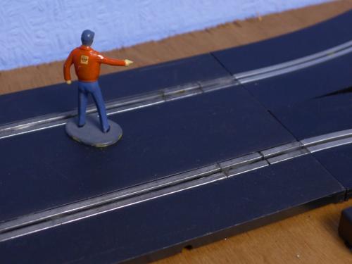
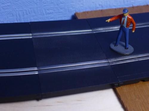
To help this fit into the space, I swapped an R3 for an R4 at the top 90-degree corner. That makes it slightly tighter - R2-R2-R3-R4 and into the R4 esses, instead of R2-R2-R4-R4. I've also squeezed an extra 1/4 straight into the steepest part of the hill, which smooths the gradient slightly. None of this has changed the driving very much at all. I'm pretty sure I now have the track as I want it for driving and to give space for scenics.
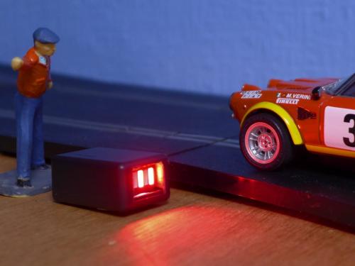
Most of what I've done the past month or so is electrics - routing all the power and data cable straight down through the road-bed; building a box for the Arduino that sits out of the way (no longer in a drawer) and building some road-side start lights that are controlled via the Arduino. This is how they work...
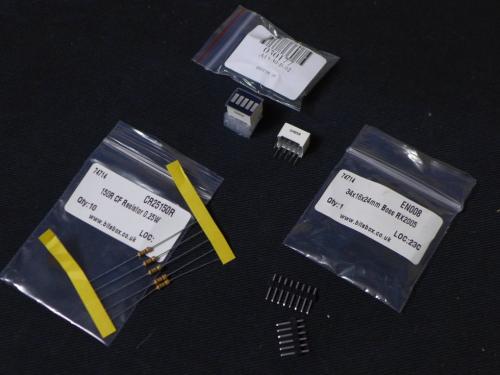
The parts list is:
- 5-Segment Red Bar LED Display for Arduino here
- 5 x 150R 0.25W resistors
- Plastic box 34 x 16 x 24mm
- Cat 5 cable (4-stranded pairs)
- Heatshrink tubing
- Header strip connectors (cut to 5 segments + 1 segment)
This is the diagram I used, which is in the 'Arduino Uno and Race Coordinator' pdf that is bundled with RC...
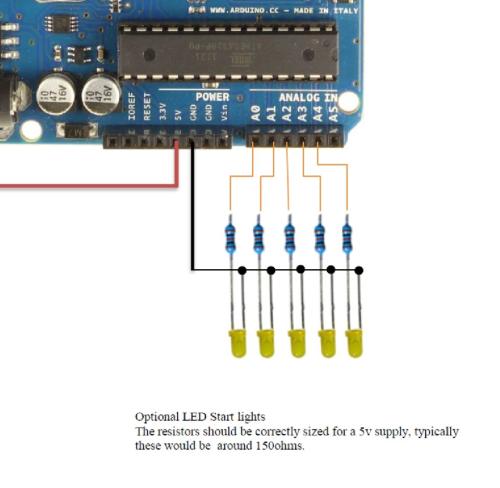
I bent the -ve pins together on the bar LED module and soldered a common ground wire to them - and this went direct to a GND socket on the Arduino, soldered to a single segment of the header strip. Each of the +ve pins had a separate wire soldered to it - and each went to the designated 'analogue in' sockets on the Arduino (A0 to A4), via a resistor and the header strip. This was quite fiddly - I ended up using the heatshrink on the end of the Cat 5 strand and over the resistor and then soldering 3mm of exposed resistor leg to the header strip. Flux and a low temperature iron was required.
It works nicely - three bars default (pre-race, yellow flag, end of race), then the countdown - and everything off when the race is running. I was going to start the box upright, but I prefer it lying down - and it's much easier to fit everything in the box like that! I've also changed my driving position to where I can admire the lights.
This month, I want to finish strengthening the road-bed and constructing the removable section for the lower loop. Naturally, I have been spending a lot of time mulling over scenery - and keep simplifying my original plans. There's a lot I like in this video...
My target is to have a week focused on starting the broad strokes of the scenery between Christmas and New Year - and then work on the detail at my leisure.



![[+]](https://slotracer.online/community/images/bootbb/collapse_collapsed.png)


