Thread Rating:
  • 0 Vote(s) - 0 Average
  • 1
  • 2
  • 3
  • 4
  • 5

Single Lane Hillclimb 'Y' Using Digital Pit Lane Pieces
#11

It's an interesting idea, I'll be keeping an eye on developments, and might even be tempted to have a go myself if the electronics aren't too complicated.

A genuine single lane track would obviously be more realistic for a rally as well as a hillclimb, and of course there are more space savings to be had by cutting off the unused power rails on some of the corners, if the track is going to be permanent.
[+] 2 members Like JasonB's post
Quote
#12

Coincidence or not, someone on the German Freeslotter is building a single lane rally loop as well. He came up with some drawings for the polarity change including a list of parts needed. I think the tread speaks for itself but the German used is easily translated.

Here’s a link: https://www.freeslotter.de/index.php?thr...rallybahn/
Quote
#13

Thanks Henk. Although I haven't translated it all, the info has appeared on various English-language slot car sites and forums in the past.

I have come across very similar wiring diagrams dating back 10-15 years - using routed track and 'old-fashioned' mechanical DPDT relays, solenoids etc. Model railroaders were certainly using this sort of set-up 40 years ago and probably slot car enthusiasts too. It has all been interesting and very useful to read, but I know from building other tracks that modern electronic components make the power control needed for projects like this much easier (and cheaper) - the model railways enthusiasts have moved on and so should we.

What the Scalextric pit lane exit and modern electronics offers is a more accessible plug & play version. Most of the circuitry in the diagram is replaced by a single board, not too difficult to put together from components or available ready-made for £4 here:  www.modellingelectronics.co.uk/products/reverse-polarity-switch-module/

When I receive and test the board I will post a picture on the thread - the wires I currently have soldered into a mechanical DPDT switch will simply screw into the terminal blocks on the board. I will add a push-to-make button attached to trigger the relay board - and then I can experiment with various lap sensing-type options to see which can most reliably replace the manual button to create an automatic system. Start simple, test, add complexity only if needed...

The other thing I did differently was to isolate the entire return loop and powered it from the driver station - that gives more time to successfully throw the polarity switch (manually or automatically). It also makes the circuitry simpler and acknowledges that slot cars run faster than trains.
[+] 1 member Likes woodcote's post
Quote
#14

Too impatient to wait for the reverse direction module from Modelling Electronics, I have been playing with the basic single-channel relay board (eg this one at bitsbox) that I'll be using to trigger the module...


I use one of these to launch the cars on my HO drag strip and use a simple momentary push switch to complete the circuit and power the strip while I'm holding the button down. So would simply attaching a wire to each rail in the 1-inch dead section on my loop give me the circuit I needed to trigger the relay in the same way? As a car crossed the dead section it would complete the circuit (irrespective of any current created by the motor), acting in the same way as the momentary push switch. So I gave it a go...


The relay board is powered by a 5 volt phone charger plug via a USB to 2.1mm DC plug (available at bitsbox here). I will also be powering the reverse direction module with this 5v supply - it should all fit neatly in a small plastic box.. but at the moment it's a bit of a mess! The output has a circuit with a motor in it, so I am not just relying on the green LED on the board telling me it's all working, I look for the circuit to work too.


I soldered a 150-ohm resistor between the cable and the relay board input on each wire. I'd tested the maximum voltage I was getting through the bare cables when a powered car crossed the dead section. Not surprisingly, the more powerful the motor, the more volts generated. The most I got was 0.25 volts.

When I placed a car on the 1-inch dead section, the green light lit up and the motor sprung into life and kept going. Rolling the car over the dead section caused the green light and motor to work from the moment the leading edge of both braids were on the dead rails, to the moment the trailing edge lost contact. Perfect. Running the car normally (at 9.5 volts via the driver station), it all happened much quicker, but the green LED and motor came on every time. And I didn't blow up the relay board (the relay is separated from the input via an opto-coupler), which was a bonus.

So all ready to go with the reverse direction module... which arrived this afternoon Thumbup 

   
[+] 5 members Like woodcote's post
Quote
#15

I have the reverse direction module working nicely with a push button - but only if I hold the button down as I go up the hill and let it go when I want to go back down...

Quote:Once the control voltage (Terminals 1 and 2) have power supplied to them the relay is activated and the output terminals of 5 and 6 will then change polarity.

Hmm, this info from the website could (and was) interpreted that applying momentary power to the relay flips the polarity / direction. In fact, a momentary burst of power only momentarily flips the polarity. The power has to stay on to maintain that change. What I need in between the dead strip (or any car-operated signal) and the reverse direction module is a latching relay. Thankfully, these are also available in similar ready-made modules. I have one on its way from a bloke in Wembley: fingers-crossed for Saturday.

In the meantime, I shall get everything tidied up...


Very pleasingly, I do have a working single-lane hillclimb / rally stage to have some fun with. The manually-operated reverse direction switch will do for now... it is a massive improvement over the mechanical switch. And when it arrives, I'll see if the latching relay is the final piece in the jigsaw for the automatic version. There might be more lessons to learn.
[+] 4 members Like woodcote's post
Quote
#16

The latching relay module (bought from eBay here) arrived at lunchtime...
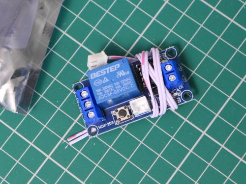
   

I wanted to avoid plugging the dead strip wires directly into the little JST socket. I kept the optocoupler relay board and connected the three modules together to protect everything from anything nasty coming from the dead strip...
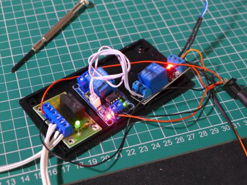
   

It complicates things a little, but it's safe - and it works!

I was delighted when I triggered the chain of three relays with the manual switch, but absolutely ecstatic when I tweaked the connections ('Normally Open' to 'Normally Closed' on the optocoupler relay board) and remembered how the deadstrip wires attach (that's very important) - and the car triggered the direction change all on its own!

I still have just the one deadstrip attached (and am using the manual switch for the lower turnaround loop), but I have tested the set-up with various cars and at high & low speed...

No problems as yet Sweating

Here's a wiring diagram of the entire layout...
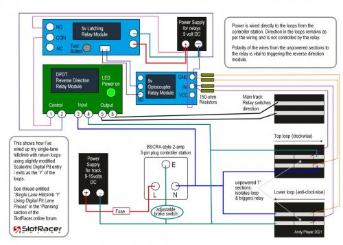
   

Click the image to make it much bigger.

Most of the connections are via screw terminals.

Here are the links to the modules again...
I used 5 volt versions, but 12 volt models are available if you wanted to power them with a 12 volt power source. I like the simplicity of the 5 volt phone charger plug and a USB to 2.1mm DC connector (Bitsbox here plus socket here).

In terms of wiring, I've used 23 AWG wire to connect the relays (stranded or solid core is fine eg Bitsbox here); twisted pairs removed from Cat5e networking cable for the dead strip 'sensors' (with a 150 ohm 1/4W Carbon Film resistor between each cable and the relay input) ; and rather beefier 42/0.2mm speaker cable (Bitsbox here) for the track power - complete overkill at 15 Amps, but it's what I use on all my layouts.

The next step is to get the lower loop's dead strip wired up and connected. Then we'll see if the direction change is fully automatic and fully reliable.

[+] 5 members Like woodcote's post
Quote
#17

An early start today - the lower loop is connected and it's all working...


I also put almost everything included in the wiring diagram in a 0.55-litre storage box to tidy up the spaghetti...


The green light you can see is on the reverse direction module and I've wired it so when it is shining green the car is ready to go down the hill. I have added a button so I can manually trigger the reverse direction module if the polarity is wrong at the start (like I did at the start of the video).


There are some finishing touches needed on the box - and I have decided to omit the adjustable brake switch - but the track is now plug-in & play anytime I want to run some cars Wrench
[+] 4 members Like woodcote's post
Quote
#18

Perfect. What comes next, the table construction or will you use a  base plate for each level?

Hub Thumbup
[+] 1 member Likes rallyhub's post
Quote
#19

Thanks Hub. Yes, the plan for the next 7 days is to drive lots of cars, finalise the track layout, tweak the elevations and then move on with constructing the benchwork. Having completed the brief for this thread, it'll all be happening over on the track build thread: https://slotracer.online/community/showt...p?tid=2053
[+] 1 member Likes woodcote's post
Quote
#20

Congratulations Andy, this is a neat solution to the polarity reversing aspect.
Does the car stutter at all when the polarity flips? Doesn't look like it does.

Leo

Forum Precepts:  Don't hijack or divert topics - create a new one.   Don't feed the Troll.    http://www.scuderiaturini.com
[+] 1 member Likes Scuderia_Turini's post
Quote


Possibly Related Threads...
Thread / Author Replies Views Last Post
Last Post by JasonB
13th-Mar-23, 12:46 PM
Last Post by 964rh
16th-Apr-21, 06:27 PM

Forum Jump:


Users browsing this thread: 2 Guest(s)