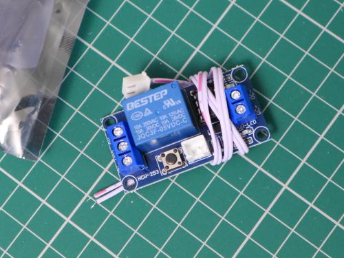
The latching relay module (bought from eBay
here) arrived at lunchtime...
I wanted to avoid plugging the dead strip wires directly into the little JST socket. I kept the optocoupler relay board and connected the three modules together to protect everything from anything nasty coming from the dead strip...
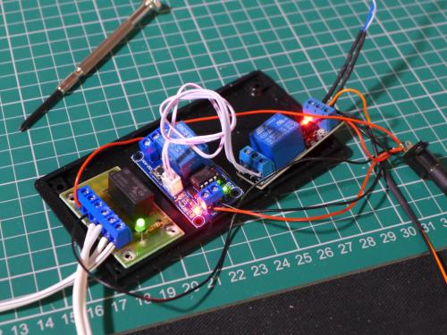
It complicates things a little, but it's safe - and it works!
I was delighted when I triggered the chain of three relays with the manual switch, but absolutely ecstatic when I tweaked the connections ('Normally Open' to 'Normally Closed' on the optocoupler relay board) and remembered how the deadstrip wires attach (that's very important) - and the car triggered the direction change all on its own!
I still have just the one deadstrip attached (and am using the manual switch for the lower turnaround loop), but I have tested the set-up with various cars and at high & low speed...
No problems as yet

Here's a wiring diagram of the entire layout...
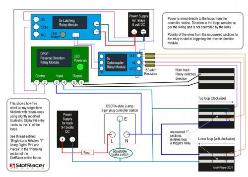
Click the image to make it much bigger.
Most of the connections are via screw terminals.
Here are the links to the modules again...
I used 5 volt versions, but 12 volt models are available if you wanted to power them with a 12 volt power source. I like the simplicity of the 5 volt phone charger plug and a USB to 2.1mm DC connector (Bitsbox
here plus socket
here).
In terms of wiring, I've used 23 AWG wire to connect the relays (stranded or solid core is fine eg Bitsbox
here); twisted pairs removed from Cat5e networking cable for the dead strip 'sensors' (with a 150 ohm 1/4W Carbon Film resistor between each cable and the relay input) ; and rather beefier 42/0.2mm speaker cable (Bitsbox
here) for the track power - complete overkill at 15 Amps, but it's what I use on all my layouts.
The next step is to get the lower loop's dead strip wired up and connected. Then we'll see if the direction change is fully automatic and fully reliable.


![[+]](https://slotracer.online/community/images/bootbb/collapse_collapsed.png)


